Sunday, 4 September 2016

DISC BRAKE BASICS – HOW DISC BRAKES WORKS

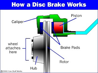
Trickling down from the motocross world, disc brakes have now become popular on off-road bicycles. Discs provide powerful and reliable braking in all types of weather and terrain so they’re ideal for trail riding. Plus, unlike rim brakes, discs aren’t compromised should you hit a hole or land hard and bend your wheel.

WORKING OF TURBOCHARGER

The turbocharger on a car applies a very similar principle to a piston engine. It uses the exhaust gas to drive a turbine. This spins an air compressor that pushes extra air (and oxygen) into the cylinders, allowing them to burn more fuel each second.


DIFFERENCE BETWEEN OPEN DIE FORGING AND CLOSED DIE FORGING

Forging Processes: Open Die Forging & Closed Die Forging

There are multiple options for metal deformation using the forging concept. The two most common processes are open and closed die forging. While similar in the basic idea of using pressure and temperature to modify material, the two types of forging are made distinct by their use of dies to form the metal.

Open Die Forging

Open die forging is the process of deforming a piece of metal between multiple dies that do not completely enclose the material. The metal is altered as the dies “hammer” or “stamp” the material through a series of movements until the desired shape is achieved. Products formed through open forging often need secondary machining and refining to achieve the tolerances required for the finished specifications. Open die forging is often used for short run forgings of parts that are simple, rather than complex, in design, such as discs, rings, sleeves, cylinders and shafts. Custom shapes can also be produced with open die forging. The repeated working of the material through the deformation process increases the strength of the grain structure. Some additional benefits of open die forging include improved fatigue resistance and strength. Open die forging also reduces voids.

Closed Die Forging

Closed die forging (also referred to as impression die forging) is a metal deformation process that uses pressure to compress a piece of metal to fill an enclosed die impression. In some closed die forging processes, a succession of impression dies are used to modify the shape of the material into the final desired shape and form. The type of material, tightness of tolerances, and need for heat treatment can determine the number of passes the product requires through the dies.
There are two types of equipment that are commonly used for closed die forging: mechanical forging presses and hydraulic forging presses.

WHAT IS AN OIL FILTER AND HOW OIL FILTERS ARE MADE

An oil filter is a filter designed to remove contaminants from engine oil, transmission oil, lubricating oil, or hydraulic oil. Oil filters are used in many different types of hydraulic machinery, but primarily in internal-combustion engines, in on- and off-road motor vehicles, light aircraft, and various naval vessels.
You’ve may have put many new filters on your car when changing the oil, but have you ever seen inside one or how and what are they made of?

About 400 million oil filters are manufactured in the USA each year. Take a look at the process of making oil filters!

Main components of a gear box:

In any device two or more component works together and fulfills the required function. In a transmission box four components are required to fulfill its function. These components are-

1. Counter shaft:

Counter shaft is a shaft which connects with the clutch shaft directly. It contains the gear which connects it to the clutch shaft as well as the main shaft. It may be run runs at the engine speed or at lower than engine speed according to gear ratio.


2. Main shaft:

It is the shaft which runs at the vehicle speed. It carries power form the counter shaft by use of gears and according to the gear ratio, it runs at different speed and torque compares to counter shaft. One end of this shaft is connects with the universal shaft.

3. Gears:

Gears are used to transmit the power form one shaft to another. They are most useful component of transmission box because the variation is torque of counter shaft and main shaft is depend on the gear ratio. The gear ratio is the ratio of the driven gear teeth to the driving gear teeth. If gear ratio is large than one, the main shaft revolves at lower speed than the counter shaft and the torque of the main shaft is higher than the counter shaft. On other hand if the gear ratio is less than one, than the main shaft revolves at higher speed than the counter shaft and the torque of the main shaft is lower than the counter shaft. A small car gear box contains four speed gear ratio and one reverse gear ratio.

4. Bearings:

Whenever the rotary motion, bearings are required to support the revolving part and reduce the friction. In the gear box both counter and main shaft are supported by the bearing.


Working of a principle gear box:

In a gear box, the counter shaft is mashed to the clutch with a use of a couple of gear. So the counter shaft is always in running condition. When the counter shaft is bring in contact with the main shaft by use of meshing gears, the main shaft start to rotate according to the gear ratio. When want to change the gear ratio, simply press the clutch pedal which disconnect the counter shaft with engine and change connect the main shaft with counter shaft by another gear ratio by use of gearshift lever. In an gear box, the gear teeth and other moving metal must not touch. They must be continuously separated by a thin film of lubricant. This prevents excessive wear and early failure. Therefor a gearbox runs partially filled with lubricant oil.

AIR CONDITIONING SYSTEM OF AN AUTOMOBILE

We all know about air conditioning system. The automotive air conditioning system is also works on the reverse Brayton or Rankine cycle. As like all air conditioning system the aim of automotive air conditioning is to control the temperature and humidity of the atmospheric air and circulate the same in the automobile. The automotive air conditioning system consists a refrigeration system, air circulation and distribution system and a control system. The refrigeration system cool down the air which include many other parts like compressor, condenser etc. The air circulating system circulate this cooled air into the car which include blower, air duct etc. The controlling system used to control the temperature of the car by sensing it and control the refrigerating system.

Principle of Car Air Conditioning System:


The automotive air conditioning system includes the compressor, condenser, evaporator, receiver-dehydrator and connecting lines which includes expansion valve, orifice tube, suction throttling valve, positive operating absolute valve, evaporator pressure regulator valve, thermal sensor, high pressure cut off switch and cycling compressor switch. In old days Freon 12 was used as refrigerant but now it is replaced by alternative refrigerant like R134a. The layout of refrigerating system is as shown in figure.

Working of Car Air Conditioning System:

The working of automotive air condition system is similar to all other air conditioning system.  The refrigerant vapour from the evaporator is compressed to high pressure by the compressor. The compressor is driven by the engine through a belt drive. It is connected by a electromagnetic clutch witch serve engage and disengage the compressor required. A variable displacement AC compressor is sometime used to match compressor capacity to varying cooling requirement.  Refrigerant pressure and temperature increases in the compressor and convert it into vapour form. This high pressure and temperature refrigerant vapour from the compressor then discharge to the condense, which is a heat exchanger situated in front of vehicle. In the condenser the refrigerant liberate heat and convert into liquid form. Sometime the ram air is not sufficient so an extra engine or electric driven fan is used to cool down the refrigerant. This cooled but high pressure refrigerant allow to pass form dehydrator to extract any moisture. Dry refrigerant liquid is then made to pass through expansion valve mounted at the inlet side of the evaporator. The expansion valve allows the refrigerant liquid to expand to low pressure in the evaporator. The process of expansion to low pressure makes the refrigerant to evaporate and thereby cool the evaporator.  A sensing devices, called temperature tube signals the diaphragm in the expansionvalve to vary orifice size depending upon the refrigerant temperature at the evaporator outlet, thus achieving automatic temperature control. The evaporator is similar in construction to the condenser.

The same circulation and distribution system as used for ventilation and heating system. The air from the blower is forced to flow over the evaporator coils which remove the latent heat of vaporization, moisture and impurities form the air. Condenser moisture with the impurities fro the evaporator drips into a try form where the same are drained out. This system is microprocessor based and depending upon input signals outside air temperature, inside air temperature, mode selection and desired temperature setting, automatically controls the air mixer valve, re-circulation valve etc.

Precaution while using car AC system:

  1. Do not use AC fresh air mode open always, since this mode is for occasional use just to release the air in circulation for a long time.
  2. Never operate AC with heater on.
  3. Never run AC without refrigerant otherwise compressor may seize.
  4. Do not leave AC joints open which may cause the moisture to enter the system.
  5. Do not charge the refrigerant in the AC system before flushing.
  6. Never switch on the AC at high speeds, which may result in the seizing of compressor.

Tips for maintenance of car AC system:

  1. Clean the condenser during normal servicing.
  2. Maintain correct refrigerant level. Less refrigerant would result in less cooling, while excessive would also result lesser cooling and excessive tripping.
  3. Top up the compressor with adequate oil.
  4. Clean the evaporator periodically.
  5. Maintain proper belt tension. A loose belt will slip whereas overtight belt would cause noise and premature compressor failure.

Difference between first angle and third angle projection


Saturday, 13 August 2016

Metal Casting Definition, Types and Processes

Definition

Casting is a method where a solid material is dissolved, heated to suitable temperature (generally treated to change its chemical structure), and is then added into a mold or cavity, which keeps it in a proper form during solidification. As a result, in just one step, complex or simple designs can be created from any material that can be dissolved. The end product can have nearly any setting the designer needs.
  • For any casting procedure, choice of right alloy, sizing, shape, thickness, tolerance, structure, and weight, is really important.
  • Special needs such as, magnetism, deterioration, stress distribution also have an impact on the selection of metal casting process.
  • Opinions of the tooling manufacturer; foundry / machine house requirements, customer's exact product needs, and secondary procedures like paint work, must be addressed before choosing the right metal casting process.

    Metal Casting Processes

    There are numerous metal casting processes implemented in the manufacturing of parts. Two main divisions can be identified by the fundamental nature of a mold they use. There is expendable casting and long-lasting mold casting. Expendable molds are utilized for a single metal casting while long-lasting molds are utilized for several. When considering manufacturing procedures, there are pros and cons to both of the processes.

    Expendable Mold

    • Can only make one metal casting
    • Made of sand, or other similar materials
    • Binders used to support material hold its shape
    • Mold that metal hardens in should be damaged to wipe out casting
    • More complex geometries are feasible for casting

    Long-lasting Mold

    • Can create many metal castings
    • Generally made of metals or often a refractory ceramic
    • It has parts that can close or open, permitting eradication of the casting
    • Have to open mold limitations part designs

    Types of Metal Casting

    Centrifugal Casting

    In this range of processes the melted material is required to disperse into the mold hole because of centrifugal speed. Centrifugal casting procedures can be categorized as true casting processes, which, when the melted material is added into the cavity, pushes it against the cavity walls where it stiffens into a hollow container; semi-centrifugal casting, varies from real centrifugal casting. In this process, the mold cavity is 100% filled with molten material so that the center, which is later on taken out, is exposed to low stress and is where inclusions and air is caught and the centrifuging approach in which melted material is poured into several mold cavities and which move around the core axis and shifted from the core axis and causes the cavities to be stuffed under excessive pressure.
  • Continuous Casting

    In this process, a flow of molten material equates of a water-cooled hole and creates a continuous rod or strip which is then chopped by a rounded saw. A new technique, generally known as circular continuous casting, entails the water-cooled hole (mold) oscillating as well as rotating at approximately 120 RPM during the casting procedure. Constant casting has an extremely high metal yield, around 98% in comparison with 87% in standard ingot-mold methods, outstanding quality of cast, manipulated grain sizes and the capability of casting unique cross-sectional designs.
  • Die Casting

    Metal Die casting processes force the molten material into the hole of a steel cavity, termed as a die, within extremely high pressure, approximately 1000 – 30,000 psi. Categorization of die casting entails the kinds of machines used, the main types being used are hot-chamber and cold-chamber machines.

Electrical Discharge Machine (EDM) Types, Advantages and Disadvantages

Electrical discharge machine is stated as a spark eroding, burning, spark machining, wire burning and die sinking equipment. This machine is used to get the desired shapes of materials by using the electrical discharges or sparks. The discharge is made between two electrodes which are separated by a dielectric liquid subject to the electric voltage. The electrodes are named the tool-electrode and the work piece electrode. The electric discharge becomes greater when the distance between the two electrodes reduces. Thus, the material gets removed from the electrodes. Fresh dielectric liquid is introduced in the inter-electrode volume. This process is also called flushing. When the current flows again the difference of potential present between the electrodes is restored before the breakdown.

EDM History 

In 1770, the impulsive effect of the electrical discharges of EDM was observed. This effect was discovered by the English physicist Joseph Priestly. The types of electrical discharge machines introduced were the Die-sink in 1943 and the Wire-cut machine in 1960s.

Definition 

The electrical discharge machine is a machine that follows some technique in order to shape the surfaces of metal objects with the help of a dielectric liquid and a tool that releases a high intensity electric discharge.

Types of Electrical Discharge Machine 

There are two types of EDM machine used commonly in today’s world:

Sinker EDM

The Sinker EDM is also called a volume EDM or cavity EDM. This has got a work piece and an electrode present in an insulating fluid. The work piece and the electrode are connected with specific supply of power. Due to the power electrical potential is created between the two components. When the electrode reaches the work piece then the dielectric discharged is released and forms a plasma channel with slight sparks.

Applications 

The sinker EDM is used when the material parts of any object requires high tolerance or corner radius. There are a lot of products and parts of those products made from Sinker EDM. Usually the production molds and dies are made with the help of this sinker EDM. It is convenient to use for making such production dies and molds.

Advantages

Sinker EDM process can do wonders for your production industry and provides durable results with high-quality finishes. Following are the advantages of Sinker EDM:
  • Cuts exotic materials easily
  • Tough materials are easy to cut
  • Little or no polishing is required after the process is complete
  • Cuts thin materials without by preventing any damage

Disadvantages

  • Excessive power consumption
  • Slow material removal
  • No or less conductive materials produced

Wire EDM 

Introduced in 1969, the Wire EDM machining is a single-strand metal wire which is pretty thin made from brass present in the workpiece and also in dielectric fluid tank. Wire EDM is used in cutting plates thick as 300mm. Apart from this, it is also used in making dies, punches and several tools from hard metals.

Applications 

Due to the flexibility of the machine the manufacturers use this to a wide range of applications. As the machine is able to cut very small pieces of materials too this is why it is a very smart choice for the production industries.

Advantages

  • Cost effective
  • High precision
  • Best for prototype manufacturing
  • Flexible machine for various cuts

Disadvantages

  • Consumes high levels of energy
  • Frequent change of brass, copper or other metal wire used in thermal stress

Ultrasonic Machining Process, Working Principles & Advantages

Ultrasonic machining is changing the manufacturing industries with its superlative performance. The main reason why this machining process is used in the manufacturing area is because it evolves less heat in the process. All the operations done with the ultrasonic machining method are cost effective and best in results. Ultrasonic machining is an abrasive process which can create any material into hard and brittle form with the help of its vibrating tool and the indirect passage of abrasive particles towards the work piece. It is a low material removal rate machining process.


Ultrasonic Machining 


It is also known as Ultrasonic impact grinding  is an operation that involves a vibrating tool fluctuating the ultrasonic frequencies in order to remove the material from the work piece. The process involves an abrasive slurry that runs between the tool and the work piece. Due to this, the tool and the work piece never interact with each other. The process rarely exceeds two pounds.

Ultrasonic Machine is Useful for Hard Material

This method is the best choice for working with hard materials such as ceramic matrix composites, ruby, piezo-ceramics, glass, ceramics, Quartz, ferrite, diamonds, technical ceramics, alumina, PCD, sapphire, CVD silicon carbide and similar ones.  

Ultrasonic Machining Process

The tool present in the machine for cutting the materials is made from a soft material as compared to the work piece. The tool is usually made from materials such as soft steels and nickel. When the tool vibrates, the abrasive slurry (liquid) is added which contains abrasive grains and particles. The abrasive slurry is added till the work pieces interacts with the grains. Due to the particles of liquid added, the work brittleness of the work piece abrades the surface meanwhile the tool deforms gradually.

Working Principle of Ultrasonic Machining 

The time spent on ultrasonic machine entirely depends on the frequency of the vibrating tool. It also depends on the size of grains of the abrasive slurry, the rigidity and the viscosity as well. The grains used in the abrasive fluid are usually boron carbide or silicon carbide as they are rigid than others. The used abrasive can be carried away easily if the viscosity of the slurry fluid is less.

Ultrasonic Machining Advantages and Disadvantages 

Get to know about the advantages and disadvantages of machining process in order to make the right decision:

Advantages

  • Machined all sorts of hard materials
  • Produces fine finished and structured results
  • Produces less heat
  • Various hole cut shapes due to vibratory motion of the tool  

Disadvantages

  • Requires a higher degree of integrity and skills
  • No certified record of radiography
  • Unnecessary large grain sizes causes defects
  • Additional repairs might be required due to spurious signs and misunderstanding of the process
Ultrasonic machines are the future of machining which is used all over the world for creating hard and brittle forms of materials for the industrial uses. A lot of operations can be performed with the ultrasonic machine which can benefit the industrialists in a variety of ways. The advanced technology creates solution which helps in opening up the market opportunities and has made things easier.  


Lathe Operations Types and Cutting Tools

Shaping up different materials and performing various functions such as sanding, deformation, cutting, facing, knurling, drilling, turning and much more is done with the lathe machines. Special tools are used in order to perform these various operations. Read on to know more about the lathe operations:

What Is Lathe?

Lathe is a machine that helps in shaping several material pieces in the desired shapes. A lathe is a machine that rotates the piece on the axis in order to perform various operations like cutting, facing, knurling, deformation and more. Metal spinning, thermal spraying, woodturning and metalworking are the common operations performed with a lathe machine. One can even shape pottery with this working wonder. Whatever material used in lathe machine whether metal or wood is molded first. The most commonly used lathes are the woodworking lathes.
The wood piece is placed in between the headstock and the tailstock of the lathe. Clamping is also used to work the piece about the axis of rotation with the help of a faceplate, clamps/dogs or collet/chuck. The products produced with the help of the lathe machine are cue sticks, musical instruments, candlestick holders, table legs, baseball bats, gun barrels, camshafts, bowls, crankshafts and much more. There are plenty of lathe that vary in sizes and shapes according to the work to be done.

Lathes Operations 

The general operations done with the lathe are grooving, turning, cutting, sanding and etc. if anyone wants to operate the lathe machine then he must first know about the feeds, cutting speed, depth of the cut and usage of tool should be considered. Each lathe operation has got its own factors that need to be considered before doing the work. The factors should be used properly so that one can avoid from mishandling and mishaps while performing any kind of lathe operation. With every cut desired the speed, depth and feed of the lathe machine is changed for precision.

Types of Lathe Operation 

The working of the lathe machine changes with every operation and cut desired. There are a lot of operations used for using the lathe machine. Some of the common lathe operations are:

Facing 

This is usually the first step of any lathe operation on the lathe machine. The metal is cut from the end to make it fit in the right angle of the axis and remove the marks.

Tapering 

Tapering is to cut the metal to nearly a cone shape with the help of the compound slide. This is something in between the parallel turning and facing off. If one is willing to change the angle then they can adjust the compound slide as they like.

Parallel Turning 

This operation is adopted in order to cut the metal parallel to the axis. Parallel turning is done to decrease the diameter of the metal.

Parting

The part is removed so that it faces the ends. For this the parting tool is involved in slowly to make perform the operation. For to make the cut deeper the parting tool is pulled out and transferred to the side for the cut and to prevent the tool from breaking.  

Lathe Cutting Tools

There are several lathe cutting tools that help in cutting with the lathe machine. The commonly used tools are mentioned below:
  • Carbide tip tools
  • Grooving tool
  • Cut-Off blade
  • Parting blades
  • Boring bar
  • Side tool


Milling Machine Definition, Process & Types

Mill Machining, Milling Process, Horizontal & Vertical Milling Machines

Definition

Milling is a process performed with a machine in which the cutters rotate to remove the material from the work piece present in the direction of the angle with the tool axis. With the help of the milling machines one can perform many operations and functions starting from small objects to large ones.
Milling machining is one of the very common manufacturing processes used in machinery shops and industries to manufacture high precision products and parts in different shapes and sizes.

Milling Machine 

The milling machines are also known as the multi-tasking machines (MTMs) which are multi-purpose machines capable of milling and turning the materials as well. The milling machine has got the cutter installed up on it which helps in removing the material from the surface of the work piece. When the material gets cooled down then it is removed from the milling machine.   

Milling Process

The milling machine involves the following processes or phases of cutting:

Milling Cutters

There are a lot of cutting tools used in the milling process. The milling cutters named end mills have special cutting surfaces on their end surfaces so that they can be placed onto the work piece by drilling. These also have extended cutting surfaces on each side for the purpose of peripheral milling. The milling cutters have small cutters at the end corners. The cutters are made from highly resistant materials that are durable and produce less friction.

Surface Finish

Any material put through the cutting area of the milling machine gets regular intervals. The side cutters have got regular ridges on them. The distance between the ridges depends on the feed rate, the diameter of the cutter and the quantity of cutting surfaces. These can be the significant variations in the height of the surfaces.

Gang Milling 

This means that more than two milling cutters are involved in a setup like the horizontal milling. All the cutters perform a uniform operation or it may also be possible that the cutter may perform distinct operations. This is an important operation for producing duplicate parts.

Types of Milling Machines 

The two main configurations of the milling machining operations are the types of milling machines. These are the vertical mill and the horizontal mill. They are further discussed below:

Vertical Milling Machines

The vertical mill has a vertically arranged spindle axis and rotate by staying at the same axis. The spindle can also be extended and performing functions such as drilling and cutting. Vertical mill has got two further categories as well: turret mill and bed mill.
The turret mill has got a table that moves perpendicularly and parallel to the spindle axis in order to cut the material. The spindle is, however, stationary. Two cutting methods can be performed with this by moving the knee and by lowering or raising the quill.
The other is the bed mill in which the table moves perpendicular to the axis of the spindle and the spindle moves parallel to its axis.

Horizontal Milling Machines

The horizontal mill is also the similar cutter but their cutters are placed on a horizontal arbor. A lot of horizontal mills have got rotary tables that help in milling in various angles. These tables are called the universal tables. Apart from this all the tools that are used in a vertical mill can also be used in the horizontal mill.